User Guide
Shearwall Pro Step-By-Step Guide:
Shearwall Pro is designed to be an easy to use lateral loads calculator for simple wood-framed buildings.
See Step By Step How to Use Shearwall Pro
How to Use Shearwall Pro
This video shows how to perform the calculations for a 30' x 40' one story shop building. It is a very simple building and illustrates the basics of how to use Shearwall Pro.
Making Shearwall Pro Drawings
This video picks up where the How to Use Shearwall Pro video ended and demonstrates how to perform a What-If analysis on the 30' x 40' shop building to find the optimized shearwall design and then how to make the shearwall drawings for your project.
Project Data
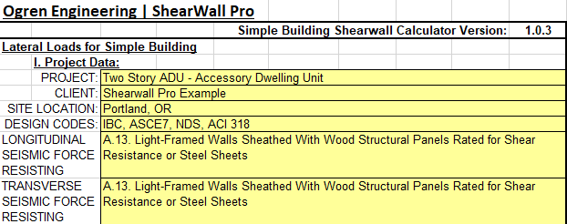
PROJECT: Enter Project Name. This is typically the project owner's name followed by the type of building it is. For example, Smith Residence, Jones Garage, or Taylor Shop.
CLIENT: This can be the name of the project owner, contractor who brought you the project, or any other identifying information for the client.
SITE LOCATION: Project address, City and State, or Subdivision with Lot Number.
DESIGN CODES: Shearwall Pro uses the IBC, ASCE7, NDS, and ACI 318 design codes.
LONGITUDINAL AND TRANSVERSE SEISMIC FORCE RESISTING SYSTEM: The IBC code requires the building type be known and assigns values used in the seismic calculations for each building type. Because Shearwall Pro is limited to use only for the type shown in the calculator, this remains fixed.
Design Criteria
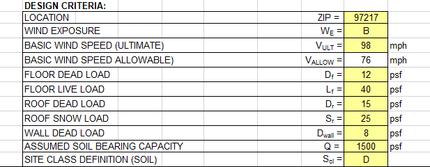
LOCATION: Enter the project ZIP Code. The IBC maps seismic design information continuously across the United States and this information is broken down by ZIP Code. Shearwall Pro requires the project ZIP Code to acquire the design seismic values.
WIND EXPOSURE: Nearly every project will be Exposure B.
WIND SPEED (ULTIMATE): The IBC defines loads at the Ultimate Level, as apposed to the Allowable Level. This means that there is a safety factor already built into the wind speed given. Look to the jurisdiction where your project is for the Basic Wind Speed and enter it here.
WIND SPEED (ALLOWABLE): Shearwall Pro calculates all forces and loads at the Allowable Level. This is an automatically converted wind speed from the Ultimate Level.
FLOOR DEAD LOAD: This is the weight of the materials used to make up the floor system. Typically, for a residential building 12 psf is used for a wood-framed floor system.
FLOOR LIVE LOAD: From ASCE7 Table 4-1.
ROOF DEAD LOAD: This is the weight of the materials used to make up the roof system. Typically, for a residential roof framing system supporting either 3-tab composite shingles or a metal roof, 15 psf is used.
ROOF SNOW LOAD: Assigned by the permitting jurisdiction the building will be built in. In some areas where snow is not a factor, ASCE7 Table 4-1 assigns a load of 20 psf Roof Live Load, which can be entered here.
WALL DEAD LOAD: A typical 2x4 or 2x6 wood-framed wall covered on both sides with either plywood or sheetrock weighs about 8 psf.
ASSUMED SOIL BEARING CAPACITY: Assigned by the permitting jurisdiction as a general assumption or this may be given by a geotechnical engineer if a site-specific report is done for this project.
SITE CLASS DEFINITION (SOIL): Seismic classification for soil type. This is typically assigned by the permitting jurisdiction.
Building Data
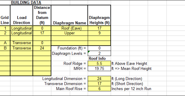
GRID LINES: Enter grid lines for the building. Every line in the building that has some significance for the lateral design of the building at any floor level needs to be defined here. Typically, letters are used to define grid lines in one direction and numbers are used to define grid lines in the orthogonal direction.
LOAD DIRECTION: For each Grid Line, select whether it is in the Longitudinal or Transverse direction with the pull down menu.
DISTANCE FROM DATUM: A datum, or "zero", needs to be selected for both the Longitudinal and Transverse directions. Typically, Grid A is the datum for one direction and Grid 1 is the datum for the other. All other grid lines are measured from them.
DIAPHRAGM NAME: Each floor/roof diaphragm needs to have a name. It is customary to name the diaphragms with the level of the building they are associated with, for example Roof | Upper | Main | Lower or Roof | 3rd | 2nd | 1st. The upper most diaphragm is set by default to be named Roof.
DIAPHRAGM HEIGHTS: Each diaphragm height is measured from the lowest diaphragm level.
ROOF INFO: Roof Ridge - Enter the height of the highest ridge above the eave. This is used to calculate the Mean Roof Height (MRH) and the roof area for wind loading. This is often the value calculated by using the roof pitch over the main portion of the roof, but not always.
Longitudinal Dimension: Looking in plan view, simple buildings can often be broken down to a main rectangle of the building. Enter the longest dimension of the main rectangle of the building here.
Transverse Dimension: Looking in plan view, simple buildings can often be broken down to a main rectangle of the building. Enter the shortest dimension of the main rectangle of the building here.
Main Roof Rise: Roof slopes are often described in terms of vertical inches of rise per 12 inches of run; this is often called the roof pitch. Enter the roof pitch here, for example if the roof pitch for your project is 4:12, enter 4 at this location.
Roof Gable Data

Roof Gable Data:
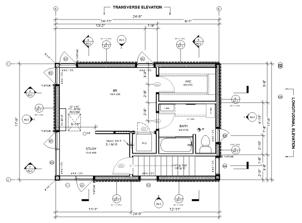
The shape of the roof needs to be defined so the proper wind loads can be calculated. In each direction, There are three sections, Left of Middle, Middle, and Right of Middle. The Left of Middle and Right of Middle sections are defined as projecting a line from the eave at the pitch of the main roof to the peak. Each section can be either Roof Surface, Wall Surface, and the Left or Right sections can be No Surface.
The elevation for each of the Longitudinal and Transverse directions is the elevation as if you are looking along the axis of that elevation.
Longitudinal Roof:
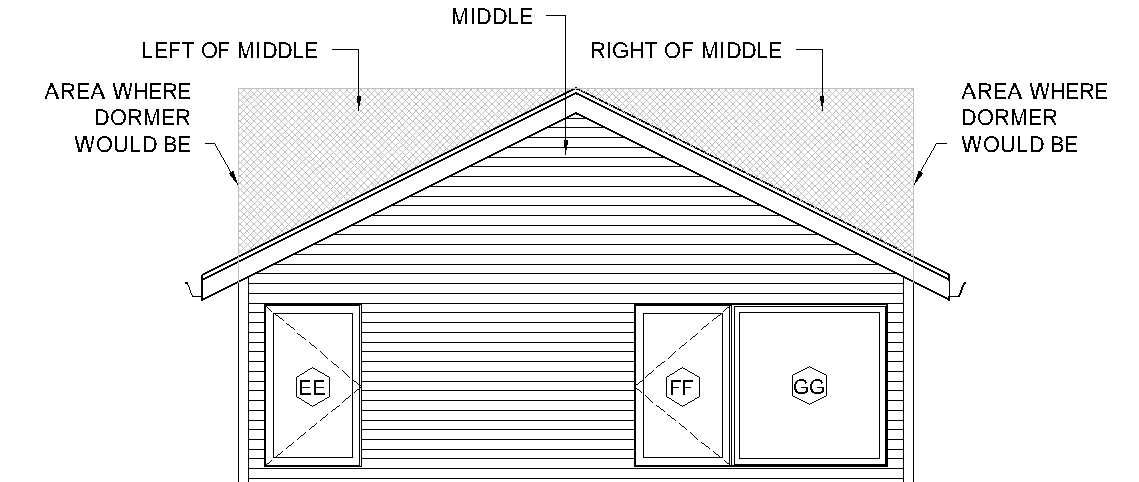
In this scenario there are not any dormers, however dormers are shown where they would be if dormers are present for this building. Because no dormers exist for this building, the selections to make are:
Left of Middle: No Surface because there is not any roof or wall surface.
Middle: Wall Surface because the middle triangle of the area above the wall top plate is a vertical wall.
Right of Middle: No Surface because there is not any roof or wall surface.
Transverse Roof
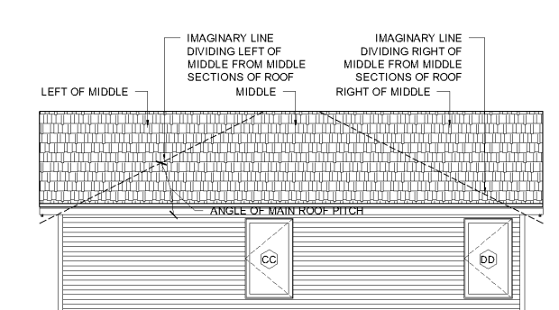
In this scenario there are not any dormers and the roof is sloping surface for the entire elevation of the building in this direction, therefore the selections to make are:
Left of Middle: Roof Surface because there is a sloping roof in this left portion of the elevation.
Middle: Roof Surface because the middle triangle of the area above the wall top plate is a sloping roof.
Right of Middle: Roof Surface because there is a sloping roof in this right portion of the elevation.
Diaphragm Data
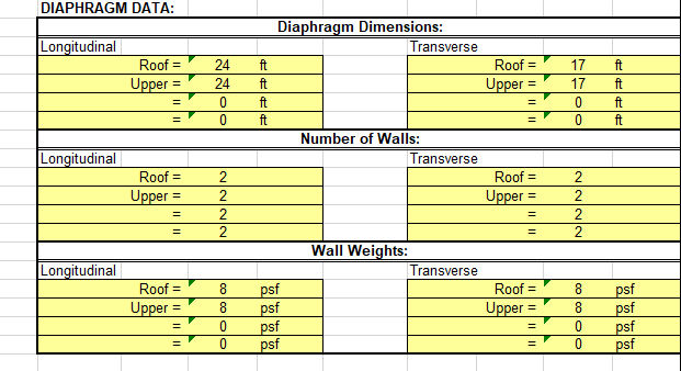
Diaphragm Dimensions: The Longitudinal and Transverse diaphragm dimensions are automatically filled in by what the Longitudinal and Transverse building dimensions are from the BUILDING DATA section above. If the diaphragm dimensions don't match what the default building dimensions are, you can change them at each level.
A common example of when the diaphragm dimensions don't match are when an upper floor cantilevers over a lower floor.
Number of Walls: Seismic loads are a function of the weight of the building, and the more walls there are in a building, the more mass/weight the building has. Count all full length/full width walls in each direction. The default is 2 to account for the exterior walls at each end of the building; increase this value as appropriate for your building.
Wall Weights: Along with the calculations taking into account the number of walls, the weight of walls needs to be accounted for as well.
Shearwalls
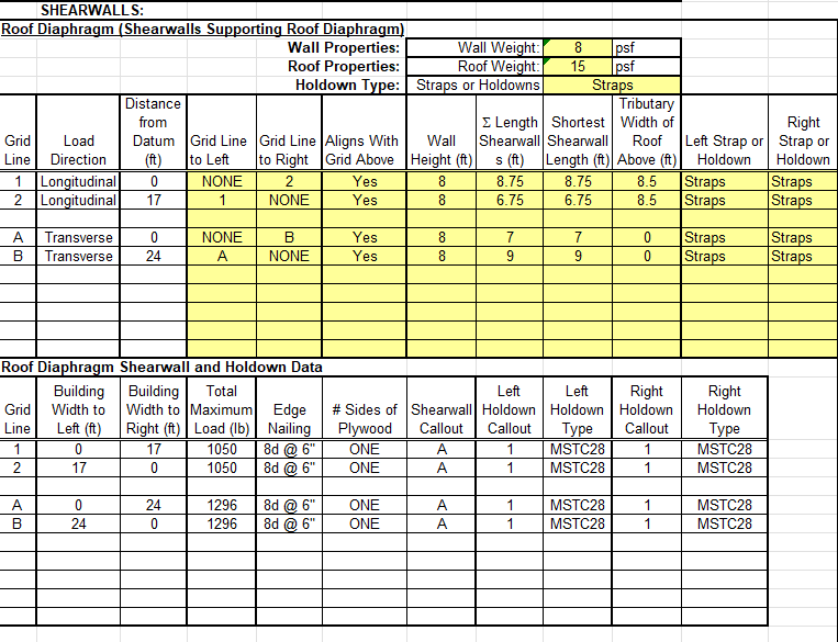
Wall and Roof Weights: The Wall and Roof Weights are copied from the loads entered above. You can modify the weight for each individual diaphragm here.
Straps or Holdowns: Changing this selection makes all of the left and right holdowns the same for every shearwall that is defined at this level. You can change the left and right holdown individually at the line of each shearwall. This is a global change for every holdown at this level.
Grid Line to Left / Right: This is where the load to each shearwall is defined by assigning the grid lines to the left and right of each individual grid.
For this tutorial, the Longitudinal Grid Lines are 1 and 2, while the Transverse Grid Lines are A and B. When assigning which grid lines are to the left and right of each one, it is easy to look at the plan view.
Grid 1: Grid to Left - None, Grid to Right - 2
Grid 2: Grid to 1- None, Grid to Right - None
Grid A: Grid to Left - None, Grid to Right - B
Grid B: Grid to A- None, Grid to Right - None
Output
As you can see in the table above, all of the shearwall type and holdown types are listed. The shearwall and holdown callouts match those that are called out in the details provided by Shearwall Pro in the members section.